home-wrecker.com
Sili-Face
history
When I began building effects, I dismissed the Fuzz Face as a circuit for Hendrix-worshippers. I had also seen much written about the complexities of proper biasing and transistor selection, which made the Fuzz Face a bit more more daunting for me, still a relative novice.
Eventually, I decided to try building a Fuzz Face. Hoping to understand the myth and mystery surrounding it, I built two identical versions: Germanium and Silicon, to hear the sonic differences on an elemental level. The gains of the transistors were all chosen based on the values presented in RG Keen's "Technology of the Fuzz Face" article at GEOfex.
Both sounded good, but I wasn't completely satisfied. I found that the Volume had to be turned up quite a bit to achieve unity with the bypassed signal. Also, in a subsequent build of a Silicon Fuzz Face, I tried high-gain 2N5088 transistors rather than searching for the low gain 2N2222 I had used earlier. When the Fuzz control was a maximum, quite a bit of hiss and oscillation was introduced. Additionally, a common complaint of Silicon Fuzz Face builders is the circuit is often susceptible to radio frequencies (RF).
improvements
I've breadboarded many different variations of the Fuzz Face design, hoping to find the version that met my criteria:However, I could not find one circuit that satisfied all my demands. I did find elements of these circuits that I thought, if combined, would result in a better Silicon Fuzz Face.
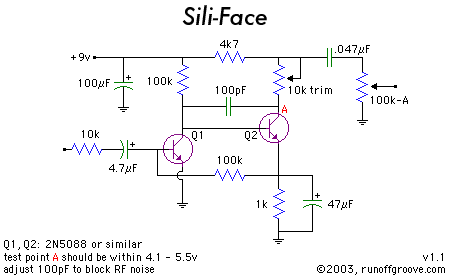
Tim Escobedo's Moreface circuits take the output directly from the collector of Q2, resulting in unity volume occuring at about 10:00 rather than 2:00 (with minimum at 7:00 and maximum at 5:00).
To block RF and other noise, Gus Smalley suggests a 10k resistor in series with the input and incorporating a power supply bypass cap.
A schematic of the Lovetone Big Cheese shows a 47pF cap between the collectors of Q1 and Q2, which supresses oscillation produced by high-gain transistors when Fuzz is at maximum.
mods
Possible modifications include adding the Gagan Pre-Gain control and/or adjusting the input/output cap values. It may be necessary, depending on your situation, to increase the 100pF capacitor. I found 47pF too low, but it worked for Gary Burchett. I experimented with values as high as 470pF. However, larger values will begin to affect the treble frequencies at output.tips
While almost any transistors worked well in my prototype of the Sili-Face, I prefer 2N5088 transistors that measure around 400 hFE.| Sili-Face transistor pin voltages (9.25v battery) | |||
| Q1 (2N4401 251hFE) | Q2 (2N5088 471hFE) | ||
| C | 1.23 | C | 4.74 |
| B | .573 | B | 1.23 |
| E | 0 | E | .605 |
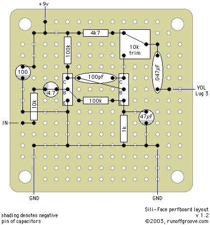
Pablo De Luca (aka Gringo) contributed a PCB layout for the Sili-Face (PDF, 154k)