home-wrecker.com
Colorsound Tonebender Professional Mark II tests
My early experiences with the Colorsound Tonebender Professional Mark II were a long and confusing ordeal, with no real answers to show for it. I first built the circuit, using Steve Daniels' schematic, in May 2001. It was my fifth or six fuzz, following two Fuzz Faces. The Tonebender design is basically a Fuzz Face with an extra gain stage. The schematic and layout can be found at Small Bear, as I mentioned above, and a schematic/layout can be found at the Green Fuz site as well.
The original circuit uses germanium transistors and they are most likely an integral part of the Tonebender's legendary sound. I had originally intended to make a silicon transistor-based Tonebender, after making a silicon Fuzz Face, but after salvaging some germaniums out of a thrift store radio, I decided to stay true to the original design.
I liked the fuzz from the circuit, but wasn't sure if I had really achieved the "Tonebender MkII sound." I did deviate from the schematic, but it was only in the way of a trimpot replacing the fixed resistor on Q3's collector. After reading volumes of internet lore regarding the proper biasing of Fuzz Faces, it seemed like a smart move.
 However, there is not any information pertaining specifically to the Tonebender MkII, so I stuck with the GEOfex Fuzz Face guidelines, biasing the Q3 collector voltage to around -4.5v. Since then, I've been endlessly searching for a really great sound by trying different biasing and swapping transistors. With all germanium transistors, the sound seemed a bit woolly to me so I tried to correct that with biasing. I didn't have much luck (at least in terms of long-term success- the Tonebender has been very much a love/hate relationship for me), so I started swapping around the transistors. The Joe Gagan EasyFace uses a silicon transistor (usually a 2N3906) for Q1 (Q2 in TBMK2), so I decided to try that in my Tonebender. The sound gained some definition and gain, but still seemed a bit ragged.
 I tried an all-silicon version, but there was no sound. It turned out that the Tonebender needs a germanium transistor for Q1. My understanding is that the silicon transistor doesn't handle the saturation well, and therefore doesn't amplify. When I recently began another session of tests with the Tonebender, I measured the voltages of Q1, which gave me direct evidence of the saturation.
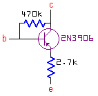
Taking a cue from Frank Clarke's Mutant Tonebender circuit, I saw that I could add in two resistors (at Q1 base and emitter) and the first stage would be essentially a Rangemaster. I measured the voltages of my Rangemaster clone, and when I added in those resistors using a silicon transistor in Q1, the circuit worked! I then moved from the breadboard to a tiny plug-in module that contained the transistor and the two resistors. By making the module (see schematic at right) rather than soldering in those new components, I could switch from stock to compensated very easily.
Below are tables of my various experiments with transistors. I've included data from my Fuzz Faces and Rangemaster, which helped me understand what exactly was happening with the Tonebender's transistors. At the bottom of the page are the results of the matched set from Small Bear.
TBMK2 Sound clips
All Germanium, but not a "matched set"
| Q1: Ge | Q2: Ge | Q3: Ge |
|---|
| C | 8.84 | .414 | 4.67 |
| B | 70 mV | .111 | .414 |
| E | 0 | 0 | .274 |
| Here you can see the saturation of Q1 pretty plainly.
| Q1: Ge
76hFE | Q2: 2N3906
152 hFE | Q3: 2N3906
147 hFE |
|---|
| C | 8.67 | 1.39 | 4.8 |
| B | 69 mV | .633 | 1.39 |
| E | 0 | 0 | .747 |
|
A Ge Q2 pulls down the B and E voltages of Q3.
| Q1: Ge
76hFE | Q2: Ge
83 hFE | Q3: 2N3906
147 hFE |
|---|
| C | 8.31 | 1.05 | 4.55 |
| B | 74 mV | .127 | 1.00 |
| E | 0 | 0 | .376 |
|
Q2 and Q3 look a lot like the Si FF here.
| Q1: Ge
76hFE | Q2: 2N2907
111 hFE | Q3: 2N3906
147 hFE |
|---|
| C |
8.31 |
1.41 |
4.62 |
| B |
74 mV |
.583 |
1.4 |
| E |
0 |
0 |
.765 |
|
The compensated Si Q1, with Ge Q2 & 3
| Q1: Comp. Si | Q2: Ge | Q3: Ge |
|---|
| C | 7.04 | .428 | 4.62 |
| B | 1.117 | .098 | .428 |
| E | .516 | 0 | .304 |
| With the EasyFace-style Q2 & Q3.
| Q1: Comp. 2N3906 | Q2: 2N3906
147 hFE | Q3: Ge
76 hFE |
|---|
| C | 7.03 | .902 | 4.6 |
| B | 1.116 | .614 | .902 |
| E | .511 | 0 | .762 |
|
All silicon, with Q1 compensated Rangemaster-style.
| Q1: Comp. 2N3906 | Q2: 2N3906
147 hFE | Q3: 2N3906
157 hFE |
|---|
| C | 7.03 | .902 | 4.64 |
| B | 1.115 | .611 | 1.415 |
| E | .511 | 0 | .751 |
|
Rangemaster
|
All Ge FF
| Q1: Ge 76 hFE | Q2: Ge 125 hFE |
|---|
| C | .641 | 4.65 |
| B | .135 | .639 |
| E | 0 | .507 |
|
Silicon FF
| Q1: 2N2222 | Q2: 2N2222 |
|---|
| C | 1.6 | 4.51 |
| B | .599 | 1.65 |
| E | 0 | 1.0 |
|
EasyFace FF
| Q1: 2N3906 | Q2: Ge |
|---|
| C | .916 | 4.58 |
| B | .609 | .917 |
| E | 0 | .751 |
|
The Matched Set I ordered a matched set of three germanium transistors for my TBMK2 from Steve Daniels at Small Bear Electronics, and they arrived today (20 March 2002). The transistors arrived in individual plastic bags with their gain written on the bag. The three bags were accompanied by a schematic of the TBMK2. The gain of my three transistors were:
68, 86, 120In anticipation of their arrival, I had set the Q3 collector trimpot in my TBMK2 to exactly 8.2k, matching the schematic. I carefully clipped the excess lead length from the transistors and inserted them into the sockets. I then measured the voltages of each transistor.
| Q1: Ge 68 | Q2: Ge 86 | Q3: Ge 120 |
|---|
| C | 8.67 | .560 | 5.07 |
| B | 82 mV | .121 | .563 |
| E | 0 | 0 | .441 |
After comparing my measurements with my unmatched germaniums data, I plugged in and played a bit. First off, let me say that I always felt that the TBMK2 at the lowest fuzz/attack setting was pretty lackluster. I had always attributed this to the similarity between the TBMK2 circuit and the Fuzz Face, whose Fuzz control set at minimum never impressed me. Straight off, the sound seemed much more focused and less ragged. I wouldn't say it was super smooth, but definitely a more fluid sound than I had ever found in my TBMK2 experiments. So, in summary, it seems that the TBMK2 does like to be in the vicinity of the -4.5V bias for Q3, much like the Fuzz Face. I highly recommend the Small Bear matched set, and wish that I had bought them earlier. Sound clips are available on the TBMK2 Sounds page (link below). |
TBMK2 Sound clips
More TBMKII Experiments
Back Home
